|
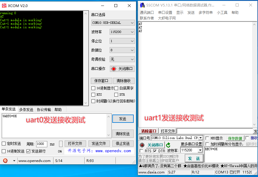
使用中我们同时开启两路串口(uart0,uart1)进行收发,这里以6621P的simple工程做示例,经过测试,大于32编号的IO口和小于32编号的IO口都可以成功配置uart0,uart1 1.配置IO口 #define PIN_UART0_TX 34//5 #define PIN_UART0_RX 33//6 #define PIN_UART1_TX 27//15 // 9 #define PIN_UART1_RX 26//16 // 10 2.uart配置如下 static void pinmux_init(void) { // KEY pinmux_config(PIN_WAKEUP_0, PINMUX_GPIO_MODE_CFG); pinmux_config(PIN_WAKEUP_1, PINMUX_GPIO_MODE_CFG); pmu_pin_mode_set(pin_wakeup_mask, PMU_PIN_MODE_PU); // UART0 pinmux_config(PIN_UART0_TX, PINMUX_UART0_SDA_O_CFG); pinmux_config(PIN_UART0_RX, PINMUX_UART0_SDA_I_CFG); // pmu_pin_mode_set(BITMASK(PIN_UART0_TX), PMU_PIN_MODE_PP);//小于32编号的IO口需要此接口 // pmu_pin_mode_set(BITMASK(PIN_UART0_RX), PMU_PIN_MODE_PU); pmu_pin_mode_set_ex(BITMASK(PIN_UART0_TX - 32), PMU_PIN_MODE_PP); // 大于等于32编号的IO口需要此接口 pmu_pin_mode_set_ex(BITMASK(PIN_UART0_RX - 32), PMU_PIN_MODE_PU); // // UART1 pinmux_config(PIN_UART1_TX, PINMUX_UART1_SDA_O_CFG); pinmux_config(PIN_UART1_RX, PINMUX_UART1_SDA_I_CFG); pmu_pin_mode_set(BITMASK(PIN_UART1_TX), PMU_PIN_MODE_PP); pmu_pin_mode_set(BITMASK(PIN_UART1_RX), PMU_PIN_MODE_PU); // LEDS pinmux_config(PIN_LED_0, PINMUX_GPIO_MODE_CFG); pinmux_config(PIN_LED_1, PINMUX_GPIO_MODE_CFG); pinmux_config(PIN_LED_2, PINMUX_GPIO_MODE_CFG); pinmux_config(PIN_LED_3, PINMUX_GPIO_MODE_CFG); pinmux_config(PIN_LED_4, PINMUX_GPIO_MODE_CFG); pinmux_config(PIN_LED_5, PINMUX_GPIO_MODE_CFG); pinmux_config(PIN_LED_6, PINMUX_GPIO_MODE_CFG); pinmux_config(PIN_LED_7, PINMUX_GPIO_MODE_CFG); pmu_pin_mode_set(pin_leds_mask, PMU_PIN_MODE_PP); } 3.uart使能,开启回调 static void peripheral_init(void) { // Init GPIO gpio_open(); // Wakeup Pin gpio_set_direction(pin_wakeup_mask, GPIO_INPUT); gpio_set_interrupt(pin_wakeup_mask, GPIO_BOTH_EDGE); gpio_set_interrupt_callback(gpio_handler); // LEDS gpio_write(pin_leds_mask, GPIO_HIGH); gpio_set_direction(pin_leds_mask, GPIO_OUTPUT); // wakeup pmu_wakeup_pin_set(pin_wakeup_mask, PMU_PIN_WAKEUP_LOW_LEVEL); pmu_wakeup_pin_register_callback(wakeup_gpio_handler, wakeup_gpio_handler); // Init UART uart_open(HS_UART0, DEBUG_UART_BAUDRATE, UART_FLOW_CTRL_DISABLED, uart0_receive_handler); uart_open(HS_UART1, DEBUG_UART_BAUDRATE, UART_FLOW_CTRL_DISABLED, uart1_receive_handler); } static void peripheral_restore(void) { #ifdef CONFIG_HS6621C // Clock For 6621C pmu_xtal32m_x2_startup(); cpm_set_clock(CPM_CPU_CLK, 64000000); cpm_set_clock_div(CPM_CPU_CLK, 1); cpm_set_clock_div(CPM_SF0_CLK, 1); cpm_set_clock_div(CPM_SF1_CLK, 1); co_delay_ms(20); // no delay will dead? #endif // Init UART uart_open(HS_UART0, DEBUG_UART_BAUDRATE, UART_FLOW_CTRL_DISABLED, uart0_receive_handler); uart_open(HS_UART1, DEBUG_UART_BAUDRATE, UART_FLOW_CTRL_DISABLED, uart1_receive_handler); } 4.main函数初始化uart0,uart1缓冲 int main(void) { #ifdef CONFIG_HS6621C // Clock For 6621C pmu_xtal32m_x2_startup(); cpm_set_clock(CPM_CPU_CLK, 64000000); cpm_set_clock_div(CPM_CPU_CLK, 1); cpm_set_clock_div(CPM_SF0_CLK, 1); cpm_set_clock_div(CPM_SF1_CLK, 1); co_delay_ms(20); // no delay will dead? #endif __set_PRIMASK(0); ble_stack_config(); hardware_init(); rwip_init(RESET_NO_ERROR); co_power_register_sleep_event(power_sleep_event_handler); log_debug("running %d\n", pmu_reboot_reason()); // dbg_mmi_enable(); memset(uart0_rxBuffer, 0, sizeof(uart0_rxBuffer)); memset(uart1_rxBuffer, 0, sizeof(uart1_rxBuffer)); // Init_Led(); // Buzzer_Enable(true); // example_spi(); appm_init(); co_timer_set(&simple_timer, 1000, TIMER_REPEAT, simple_timer_handler, NULL); while (1) { rwip_schedule(); } } 5.uart0,uart1接收和发送文件 #include "communicate.h" #include "led.h" extern uint8_t led_flag; static co_timer_t uart0_timer; static co_timer_t uart1_timer; uint8_t uart0_rxBufferLen = 0; uint8_t uart0_rxBuffer[512]; uint8_t uart1_rxBufferLen = 0; uint8_t uart1_rxBuffer[512]; #define TIMER_UART_RX_TIMEOUT_PEROID 20//5//10// #define CLEAR_BUFFER0 memset(uart0_rxBuffer, 0, sizeof(uart0_rxBuffer));uart0_rxBufferLen = 0; #define CLEAR_BUFFER1 memset(uart1_rxBuffer, 0, sizeof(uart1_rxBuffer));uart1_rxBufferLen = 0; /********************************************************************* * GLOBAL VARIABLES */ void uart0SendData(uint8_t *buf, unsigned length){ CLEAR_BUFFER0; uart_send_block(HS_UART0, buf, length); } void uart0Rx_timer_handler(co_timer_t *timer, void *param){ if(memcmp(uart0_rxBuffer,"UART0=OK", strlen("UART0=OK"))==0){ Led_style_work(1, 0, 20, 20, 4); uint8_t sendBuffer[] = {"AT\r\n\0"}; uart0SendData(sendBuffer, strlen((char *)sendBuffer)); } else{ CLEAR_BUFFER0; } } void uart0_receive_handler(uint8_t data) { // Get data uart0_rxBuffer[uart0_rxBufferLen++] = data; co_timer_del(&uart0_timer); co_timer_set(&uart0_timer, TIMER_UART_RX_TIMEOUT_PEROID, TIMER_ONE_SHOT, uart0Rx_timer_handler, NULL); } void uart1SendData(uint8_t *buf, unsigned length){ CLEAR_BUFFER1; uart_send_block(HS_UART1, buf, length); } void uart1Rx_timer_handler(co_timer_t *timer, void *param){ if(memcmp(uart1_rxBuffer,"RECV=OK", strlen("RECV=OK"))==0){ Led_style_work(1, 0, 20, 20, 4); log_debug("Cat-1 module is working!\n"); uint8_t sendBuffer[] = {"AT\r\n\0"}; uart1SendData(sendBuffer, strlen((char *)sendBuffer)); } else if(memcmp(uart1_rxBuffer,"TEST_RECV_BYTE=OK", strlen("TEST_RECV_BYTE=OK"))==0){ log_debug("Cat-0 module is working!\n"); Led_style_work(1, 0, 20, 20, 4); uint8_t sendBuffer[] = {"TEST_RECV\r\n\0"}; uart1SendData(sendBuffer, strlen((char *)sendBuffer)); } else{ CLEAR_BUFFER1; } } void uart1_receive_handler(uint8_t data) { // Get data uart1_rxBuffer[uart1_rxBufferLen++] = data; co_timer_del(&uart1_timer); co_timer_set(&uart1_timer, TIMER_UART_RX_TIMEOUT_PEROID, TIMER_ONE_SHOT, uart1Rx_timer_handler, NULL); } 6.测试情况截图如下:
|
 communicate-202502227272.c


