|
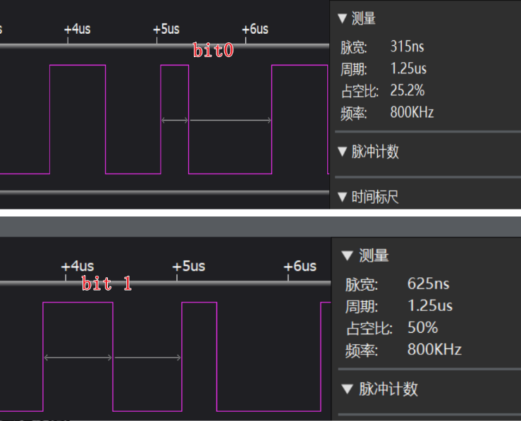
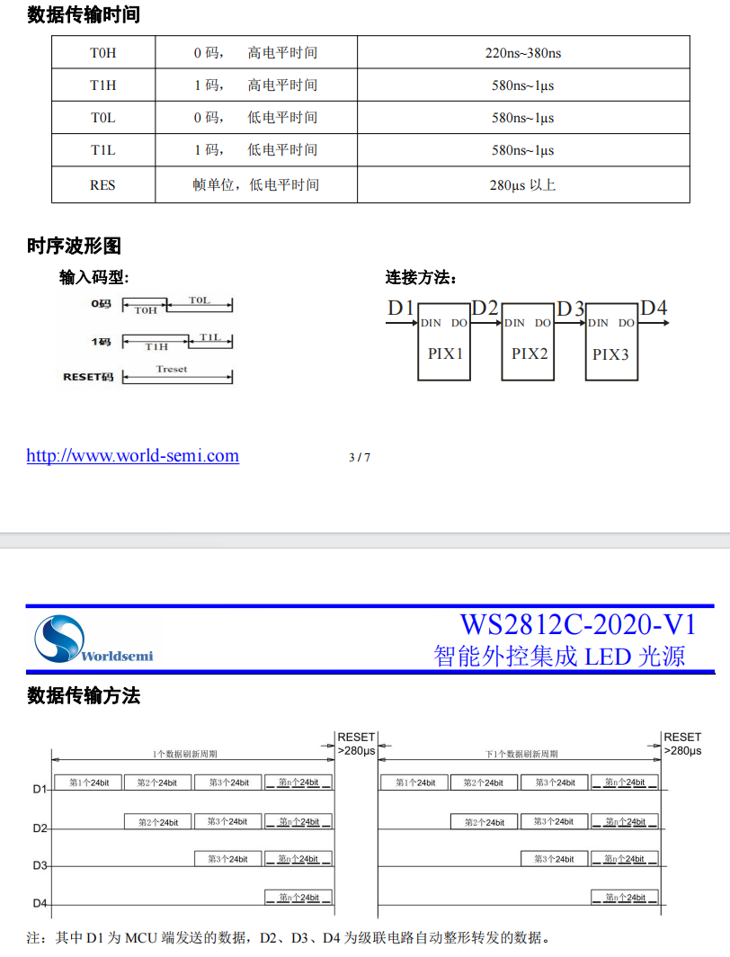
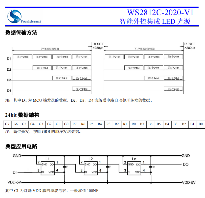
WS281x 系列如 WS2812B/WS2812C 等,串行LED控制需要较为精准的时序控制,以实现精确的调光效果。 总的解决思路: 把需要发数的控制数据转化成占空比不同的PWM波形,利用DMA FIFO 不间断发送出去。 PWM频率 为 64Mhz/80=800K , 周期为:1/800Khz=1250ns bit 0占空比: 25% 约315ns bit 1占空比为 50%,约625ns
6621Cx 经过验证的实现代码如下 #include "rwip_config.h" // RW SW configuration #include "arch.h" // architectural platform definitions #include <stdlib.h> // standard lib functions #include <stddef.h> // standard definitions #include <stdint.h> // standard integer definition #include <stdbool.h> // boolean definition #include <stdio.h> #include <string.h> #include "rwip.h" // RW SW initialization #include "dbg.h" #include "peripheral.h" #include "sysdump.h" #include "app.h" #include "board_def.h" void timer0_handler(void); #define LED_Number 15 // #define PWM_BUFF_SIZE (LED_Number * 8 * 3+1) //定义DMA_PWM 缓存大小 CO_ALIGN(4) uint16_t led_pwm_buffer[PWM_BUFF_SIZE] = {0}; static dma_fifo_t ccr_dma_fifo; HS_DMA_CH_Type *dma_ch1 = NULL; void led_dimming(void); void RGB_to_PWM_Data(void) { int led_n; int rgb_n; int bit_n; uint8_t bit_mask; uint8_t color; int buffer_count = 0; uint16_t pwm_duty; uint8_t led_colors[15][3] = { {0x10, 0x00, 0xc0}, //led00 R-G-B {0x11, 0x01, 0xc2}, //led01 R-G-B {0x12, 0x02, 0xc4}, //led02 R-G-B {0x13, 0x03, 0xc6}, //led03 R-G-B {0x14, 0x04, 0xc8}, //led04 R-G-B {0x15, 0x05, 0xca}, //led05 R-G-B {0x16, 0x06, 0xcc}, //led06 R-G-B {0x17, 0x07, 0xce}, //led07 R-G-B {0x18, 0x08, 0xd0}, //led08 R-G-B {0x19, 0x09, 0xd2}, //led09 R-G-B {0x1a, 0x10, 0xd4}, //led10 R-G-B {0x1b, 0x11, 0xd6}, //led11 R-G-B {0x1c, 0x12, 0xd8}, //led12 R-G-B {0x1d, 0x13, 0xda}, //led13 R-G-B {0x1e, 0x14, 0xdc} //led14 R-G-B }; for (led_n = 0; led_n < 15; led_n++) { for (rgb_n = 0; rgb_n < 3; rgb_n++) { bit_mask = 0x80; color = led_colors[led_n][rgb_n]; for (bit_n = 0; bit_n < 8; bit_n++) { if (color & bit_mask) { pwm_duty = 40;//80*50% H625/L625ns } else { pwm_duty = 20;//80*25% H310/L940ns } led_pwm_buffer[buffer_count++] = pwm_duty; bit_mask >>= 0x01; } } } led_pwm_buffer[buffer_count] = 0x00; //set the last pulse-duty to 0 } static co_timer_t file_buffer_timer; static void dma_cb1(dma_status_t status, uint32_t cur_src_addr, uint32_t cur_dst_addr, uint32_t xfer_size) { timer0_handler(); } typedef struct { uint32_t pin_index; pinmux_t pin_function; gpio_direction_t io_direct; pmu_pin_mode_t io_mode; gpio_trigger_type_t int_trigger_type; pmu_pin_wakeup_type_t wakeup_type; gpio_level_t default_level; } gpio_setting_t; static void gpios_init(gpio_setting_t *gpio_setting) { uint32_t pin_idx; uint32_t Bitmask; pin_idx = gpio_setting->pin_index; pinmux_config(pin_idx, gpio_setting->pin_function); } /* GPIO初始化配置 */ static void ledHalGPIO_Init(void) { int i; gpio_setting_t PWM_Buzzer_IOs[] = { {io_ctrl_a, PINMUX_TIMER1_IO_0_CFG, GPIO_OUTPUT, PMU_PIN_MODE_PP, GPIO_TRIGGER_DISABLE, PMU_PIN_WAKEUP_DISABLE, GPIO_LOW}, }; for (i = 0; i < sizeof(PWM_Buzzer_IOs) / sizeof(gpio_setting_t); i++) { gpios_init(&PWM_Buzzer_IOs[i]); } } typedef struct { /// DMA fifo buffer bool use_fifo; void *buffer; uint32_t buffer_len; dma_llip_t *block_llip; uint32_t block_num; /// Absolute address of the TIM register to access __IO uint32_t *tim_addr; /// number of registers under updating uint32_t num; // DMA burst length /// TIM DMA request source: TIM_DIER_UDE, TIM_DIER_CC1DE, ..., TIM_DIER_TDE uint32_t req; /// DMA event callback dma_callback_t callback; } timer_dma_config_t; #define BLOCK_NUM 1 DMA_DECLARE_LLIP(dma_block_llip, BLOCK_NUM); /*-------------------- PWM Dma config... *--------------------*/ timer_dma_config_t pwm_dma_cfg1 = { .use_fifo = true, .buffer = &led_pwm_buffer[0], .buffer_len = sizeof(led_pwm_buffer), .block_llip = dma_block_llip, .block_num = BLOCK_NUM, .tim_addr = &HS_TIM1->CCR[0], .num = 1, .req = (1 << 8), .callback = dma_cb1, }; static HS_DMA_CH_Type *timer_dma_config(HS_TIM_Type *tim, HS_DMA_CH_Type *dma, const timer_dma_config_t *config) { dma_id_t dma_id; if (dma == NULL) dma = dma_allocate(); dma_id = tim == HS_TIM0 ? TIMER0_DMA_ID : (tim == HS_TIM1 ? TIMER1_DMA_ID : TIMER2_DMA_ID); if (dma) { bool res; dma_config_t m_dma_config; m_dma_config.slave_id = dma_id; m_dma_config.direction = DMA_MEM_TO_DEV; m_dma_config.src_addr_width = DMA_SLAVE_BUSWIDTH_16BITS; m_dma_config.dst_addr_width = DMA_SLAVE_BUSWIDTH_16BITS; m_dma_config.src_burst = DMA_BURST_LEN_1UNITS; m_dma_config.dst_burst = DMA_BURST_LEN_1UNITS; m_dma_config.dev_flow_ctrl = false; m_dma_config.priority = 0; m_dma_config.callback = config->callback; m_dma_config.lli.enable = true; m_dma_config.lli.use_fifo = config->use_fifo; m_dma_config.lli.src_addr = (uint32_t)config->buffer; m_dma_config.lli.dst_addr = (uint32_t)&tim->DMAR; m_dma_config.lli.block_num = config->block_num; m_dma_config.lli.block_len = config->buffer_len / config->block_num; m_dma_config.lli.llip = config->block_llip; res = dma_config(dma, &m_dma_config); if (!res) { dma_release(dma); return NULL; } tim->DCR = ((config->num - 1) << 8) | ((uint32_t)config->tim_addr - (uint32_t)tim) / 4; tim->DIER |= config->req; } return dma; } static void ledHalTimer_Init(void) { const tim_config_t pwm_cfg = { .mode = TIM_PWM_MODE, .config.pwm = { // 64M 4000 16Khz .count_freq = 64 * 1000 * 1000, .period_count = 80, //800KHz=64Mhz/80 .channel = { // duty cycle = pulse_count/period_count {true, {TIM_PWM_POL_HIGH2LOW, 0}}, // channel0: duty cycle {false, {TIM_PWM_POL_HIGH2LOW, 5000}}, // channel1: duty cycle {false, {TIM_PWM_POL_HIGH2LOW, 5000}}, {false, {TIM_PWM_POL_HIGH2LOW, 5000}}, }, .callback = NULL, }, }; tim_init(); tim_config(HS_TIM1, &pwm_cfg); // NVIC_SetPriority(TIM1_IRQn, IRQ_PRIORITY_HIGH); HS_TIM1->RCR = 0x0; // reapeat ; HS_TIM1->CNT = 0x0; // reapeat ; HS_TIM1->CCR[0] = 0; } static void ledHalDMA_Init(void) { dma_fifo_init(&ccr_dma_fifo, led_pwm_buffer, sizeof(led_pwm_buffer)); dma_init(); dma_ch1 = timer_dma_config(HS_TIM1, dma_ch1, &pwm_dma_cfg1); // NVIC_SetPriority(DMA0_IRQn, IRQ_PRIORITY_HIGH); } void ledHal_Init(void) { /* GPIO初始化配置 */ ledHalGPIO_Init(); /* Timer初始化配置 */ ledHalTimer_Init(); /* DMA初始化配置 */ ledHalDMA_Init(); } void timer0_handler(void) { tim_stop(HS_TIM1); if (NULL != dma_ch1) { dma_stop(dma_ch1); dma_release(dma_ch1); dma_ch1 = NULL; } ledHalGPIO_Init(); ledHal_Init(); log_debug("\r\nled_dimming_stop"); } void led_dimming(void) { log_debug("\nled_dimming_start..."); ledHal_Init(); dma_start_with_lli(dma_ch1); HS_TIM1->CNT = 0; HS_TIM1->CR1 |= TIM_CR1_CEN; /*timer starts running*/ } void led_dimming_test(void) { RGB_to_PWM_Data(); led_dimming(); } |
 6621cx PWM调光(WS281X)-202309097053.rar


